Miniature Sand-Column Installation Tool
This special tool enables in-flight construction of sand columns in a centrifuge model, with a dry fill displacement process, similar to the bottom feed vibro-displacement method (Pooley 2013). In-flight construction is important to correctly model the stress path in the soil, allowing realistic simulation of the compaction process, during initial insertion of the pile driver and subsequent cyclic compaction.
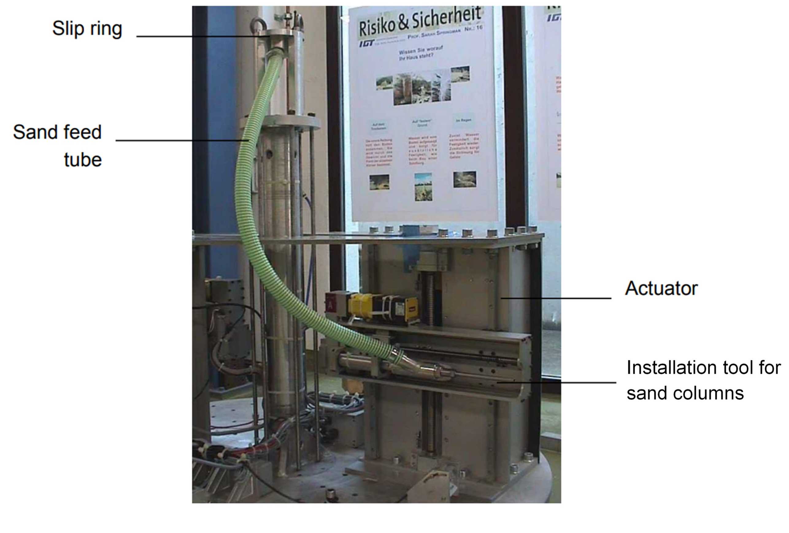
The tool consists of a mounting on the actuator, a transition piece, and a long filling tube of 10 mm diameter. A flexible plastic hose, leading from the transition piece to the centre of the tool platform, delivers the sand through a coupling from outside the centrifuge. To prevent clogging of the filling tube with clay during pile production, a lost tip system is used. This involves placing a drawing pin into the clay surface, at precisely the position where each pile should be constructed. The metal tube is positioned above the drawing pin and then driven radially outwards, pressing the pin into the clay to the required depth. The cap of the drawing pin closes the end of the filling tube, preventing clay ingress.
Dry sand is poured from outside the centrifuge down into the plastic feed pipe, and from there it flows radially along the metal tube to fill the cavity made in the clay. The metal tube is withdrawn and re-inserted incrementally, to compact the sand. Each compaction cycle consists of driving the compaction tool 10 mm backward (withdrawal) and then 5 mm forward (re-insertion), thus the tool retreats 5 mm from the soil with each cycle. The number of compaction cycles depends on the soil depth and pile length.