Geotechnical Centrifuge Center
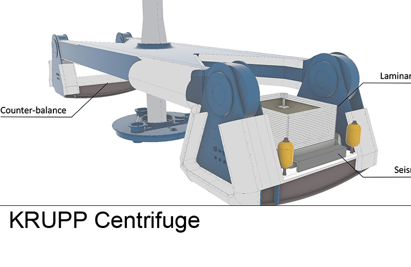
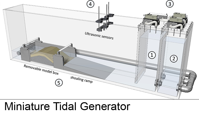
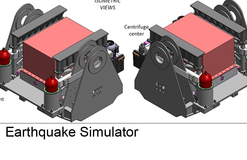
Physical modelling is indispensable to derive insights on the key factors affecting the performance of geotechnical systems, to properly validate numerical models, and to evaluate the efficiency of innovative solutions (proof-of-concept). The Geotechnical Centrifuge Center (GCC) encompasses two geotechnical centrifuges, a 9 m diameter (500gton capacity) beam centrifuge and a 2.2 m diameter (440gton capacity) drum centrifuge, a cutting-edge earthquake simulator, a Miniaturized Tidal Generator (MTG), and a variety of actuators, tool platforms, and highly specialized devices and sensors. Our experimental infrastructure is predominantly used for research and teaching purposes. On demand, we also offer highly-specialized consulting services to the industry.
Beam Centrifuge
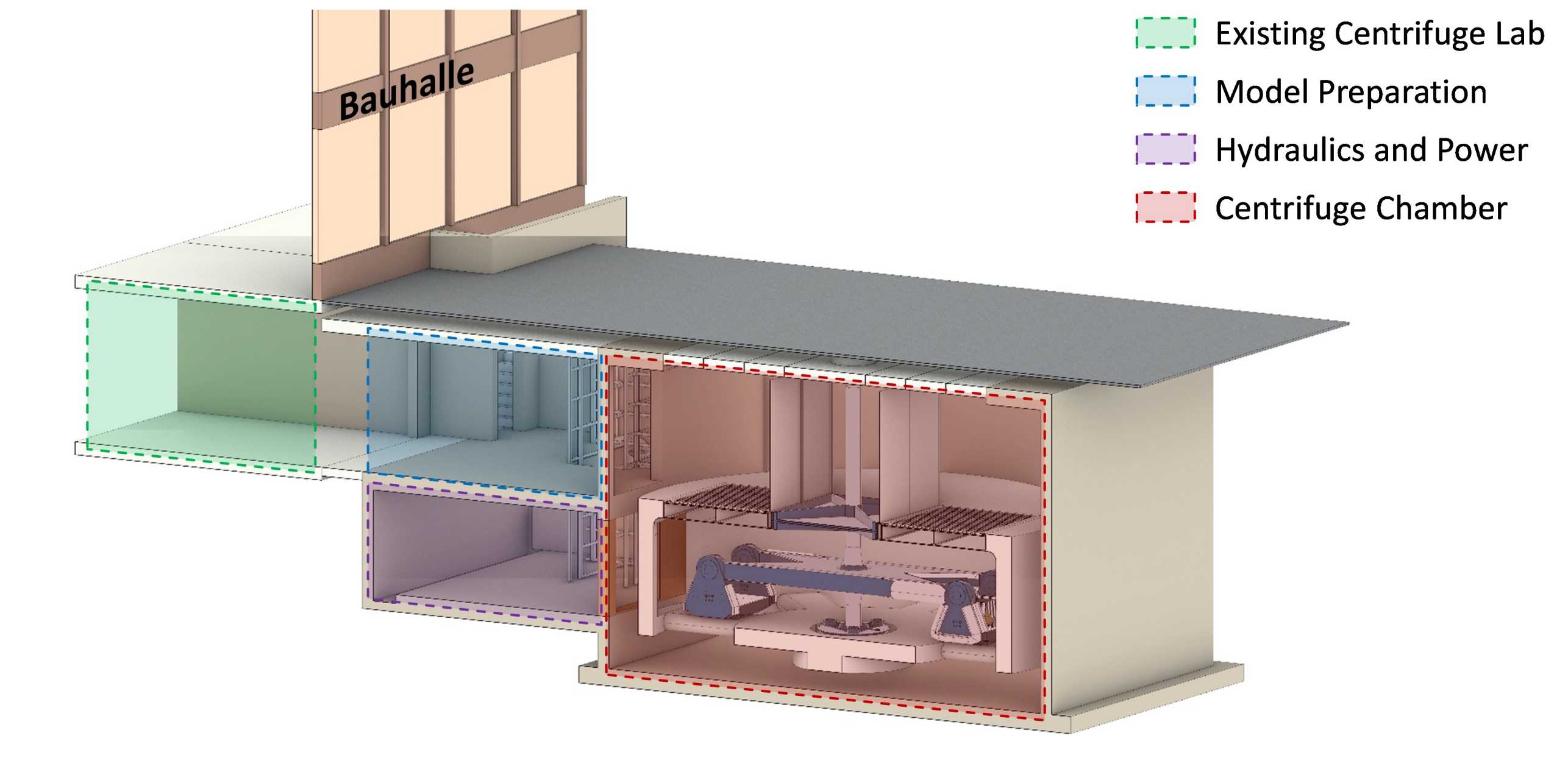
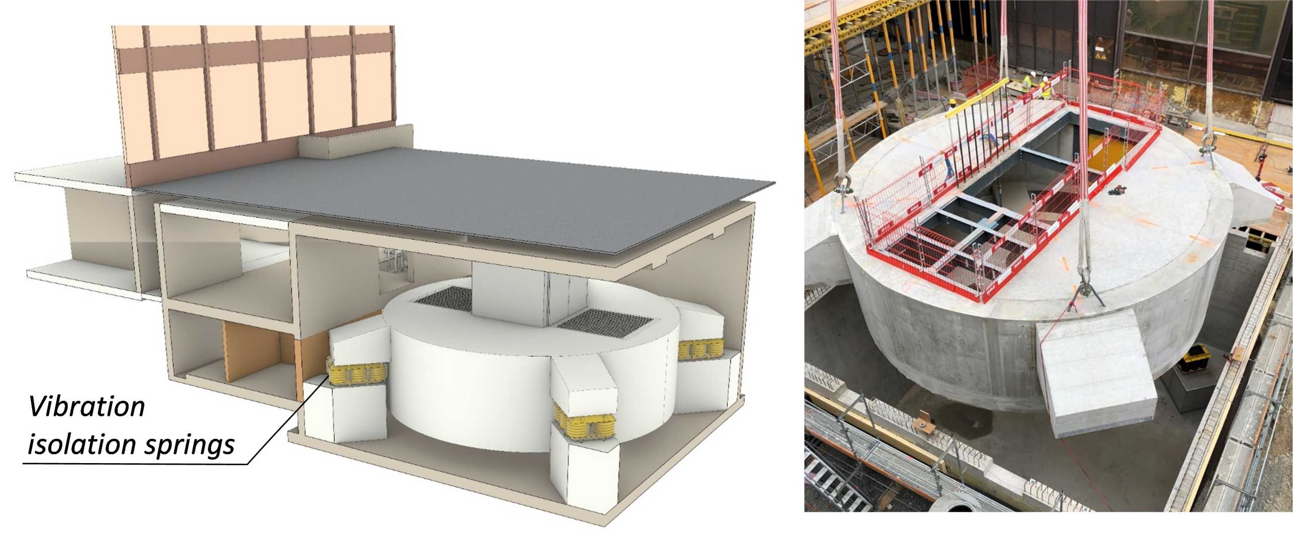
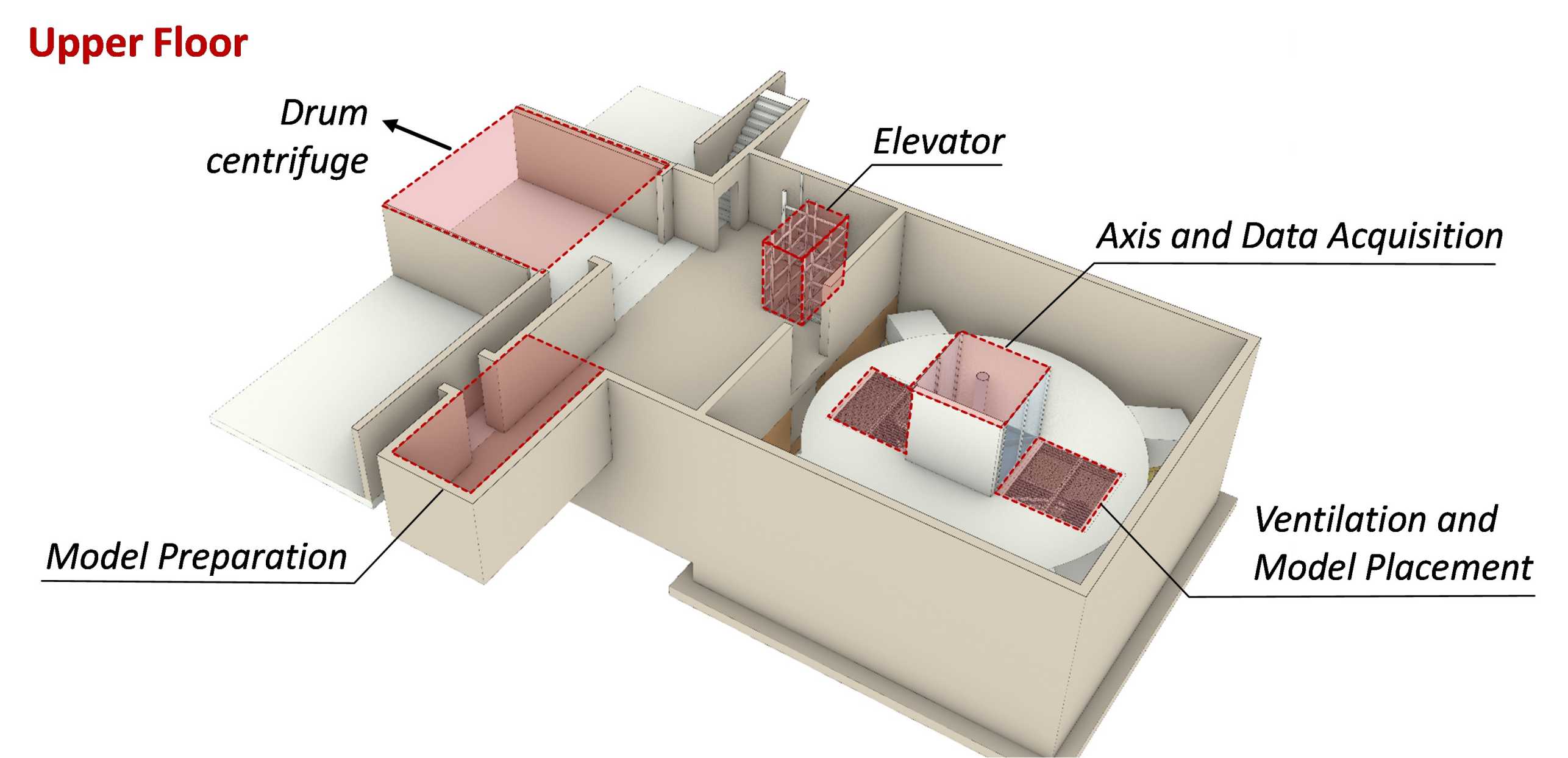
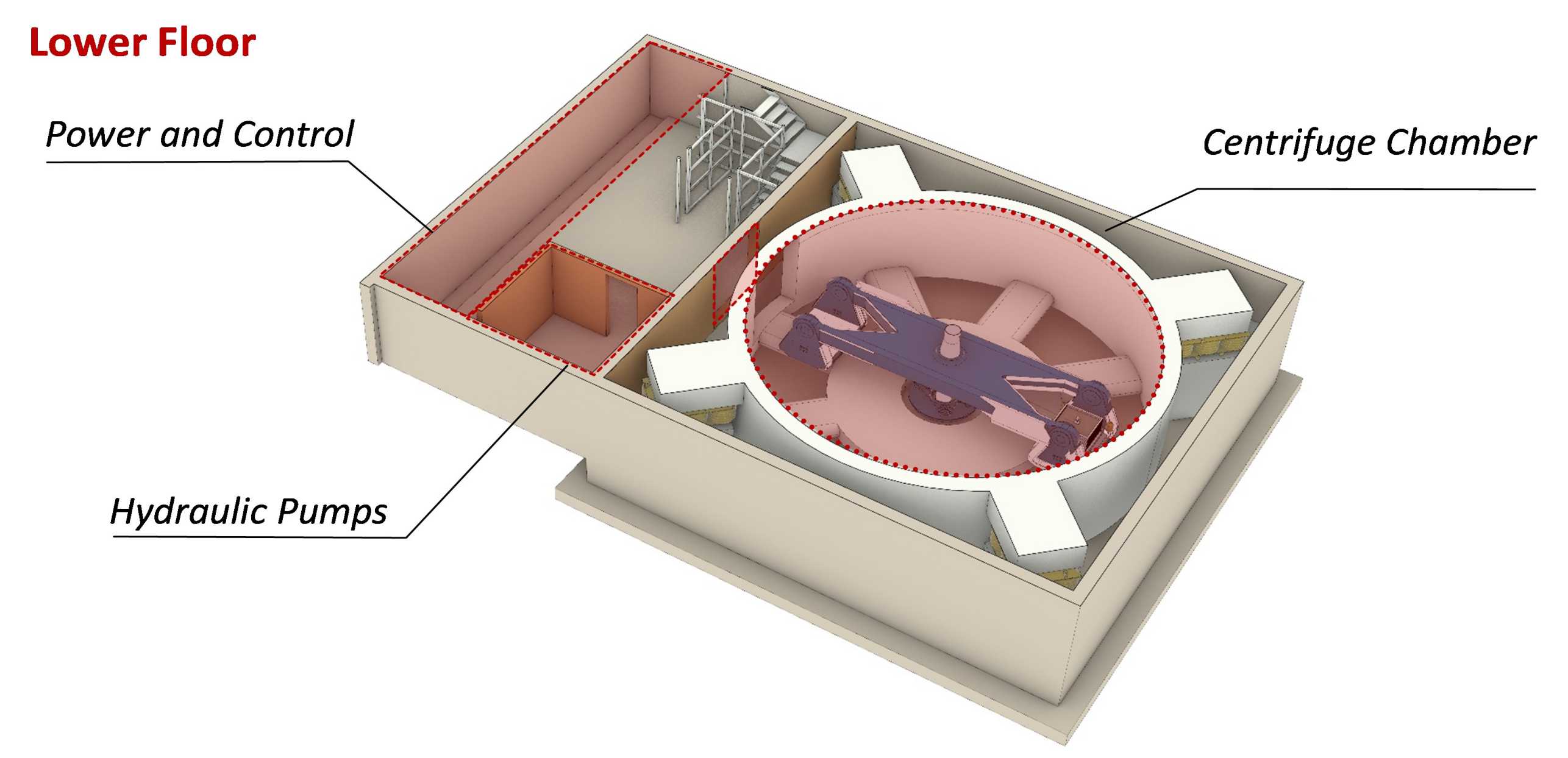
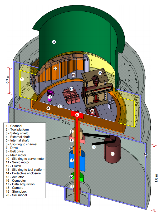
The newly-constructed beam centrifuge facility is connected to the pre-existing drum centrifuge facility on its upper floor, with the beam centrifuge installed on the lower floor. Besides the centrifuge chamber, the lower floor houses the hydraulic pumps (necessary for the supply of oil pressure to the hydro motors of the centrifuge and for the seismic shaker), as well as power and control units. The upper floor encompasses the model preparation laboratory, the housing of the upper axis with the corresponding slip-rings, and storage space. The control room is integrated in the pre-existing drum centrifuge facility, following the security guidelines of Cambridge University (Schofield, 1980) to ensure safe operation.
Click on the images below to explore each subcategory.
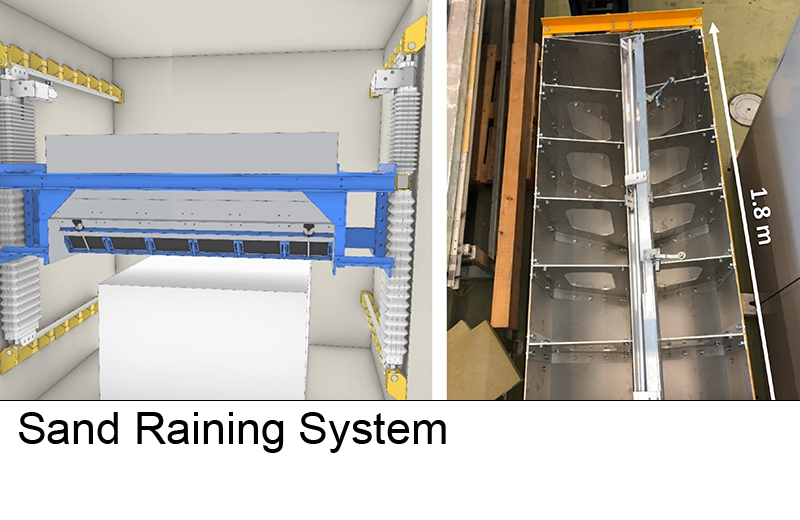
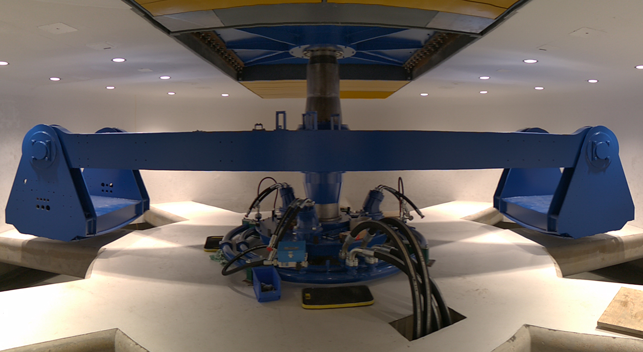
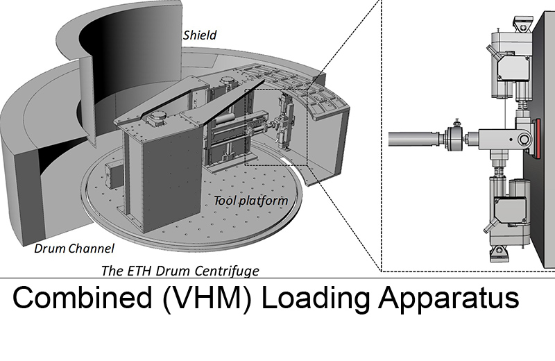
Drum Centrifuge
Established by Prof. Sarah Springman in 1999, the geotechnical drum centrifuge facility consists of a preparation laboratory, the centrifuge pit, and a control room, from which the technician, the project engineer and the proof engineer supervise the progress of the test (external page Springman et al. 2001). These three roles are based on the security guidelines at Cambridge University (Schofield, 1980) to ensure safe operation of the facility.
Click on the images below to explore each subcategory
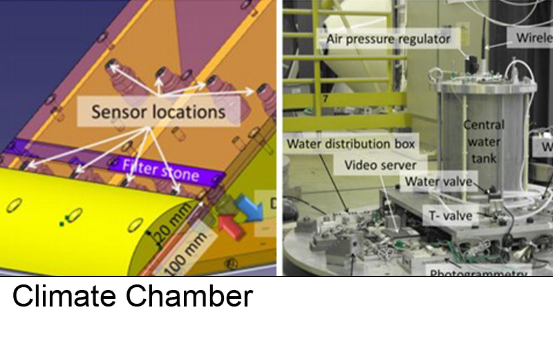
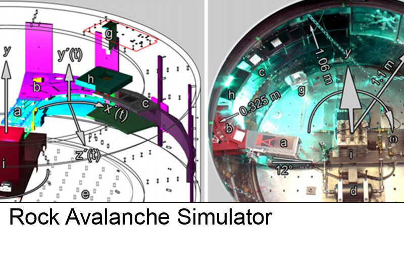
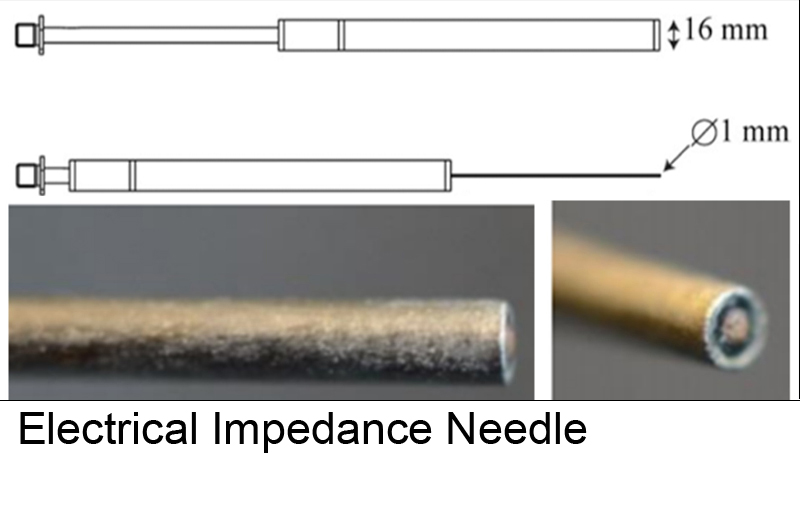
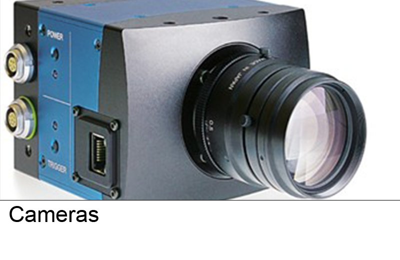
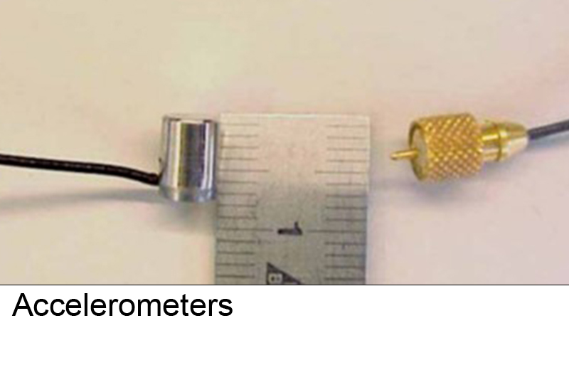
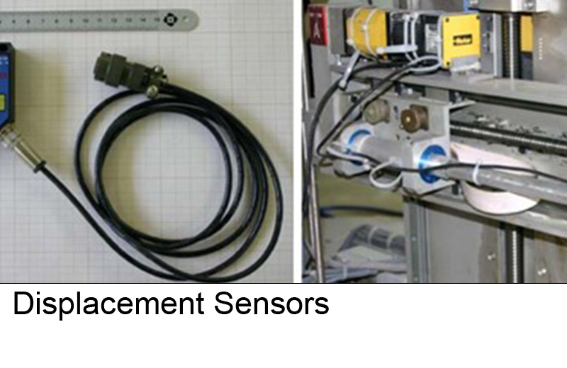
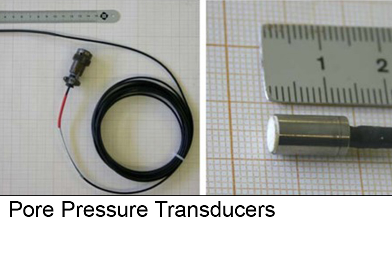
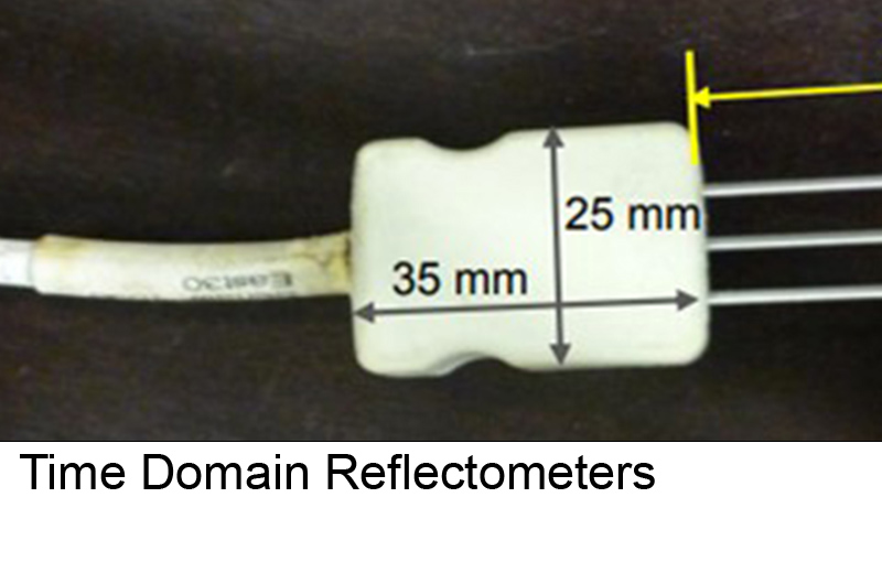
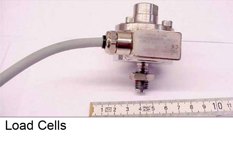
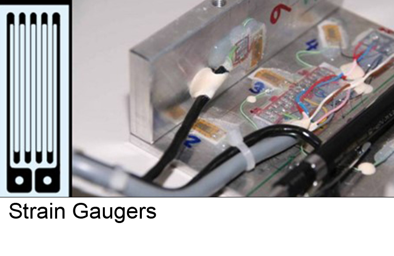
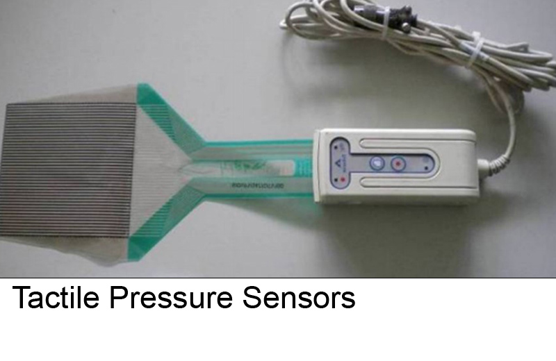
Sensors
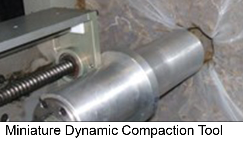
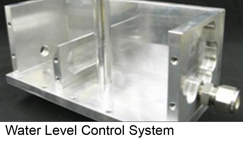
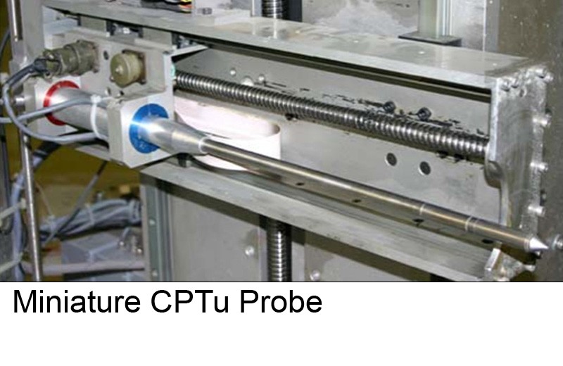
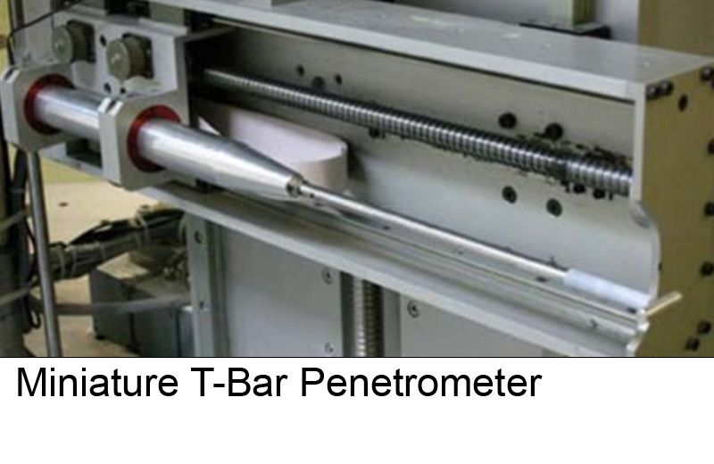
The Geotechnical Centrifuge Centre is equipped with a multitude of sensors, including high speed and high resolution cameras, accelerometers, displacement sensors, pore-pressure transducers, time-domain reflectometers, load cells, strain-gauges, and tactile pressure sensors.
Click on the images below to explore each subcategory