Water Level Control System
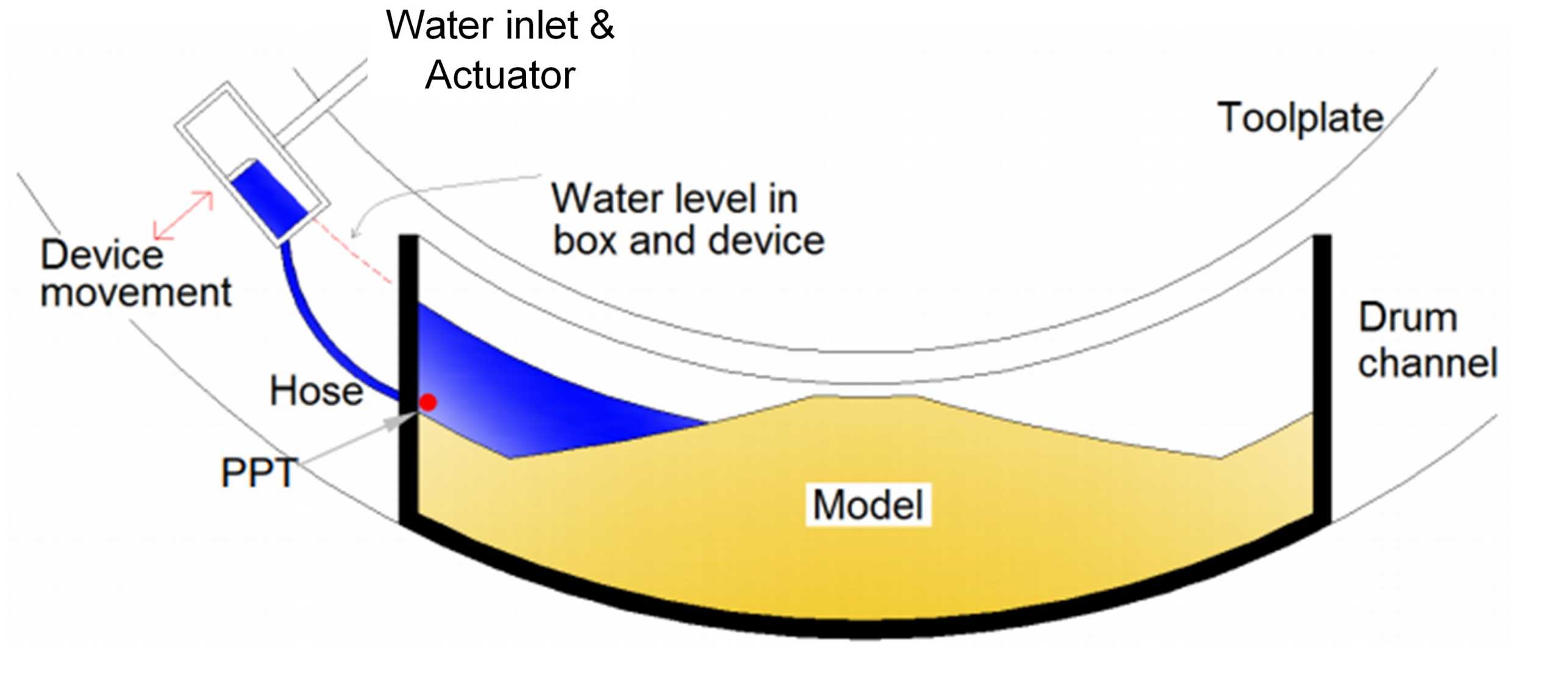
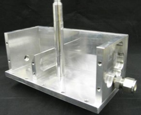
Initially developed to study the response of river dykes to transient water-level conditions, the water level control (WLC) system allows in-flight simulation of transient cycles of increasing and decreasing water level (Morales 2014). It encompasses a two-chamber 1.22lt water tank, with a maximum discharge rate of 500 ml/s. The externally supplied water flows continuously through a pipe into the first chamber of the tank. When the water level in the first chamber reaches the height of the separation wall, it overflows into the second chamber, thus allowing drainage of the system. In this way, a fixed water level can be maintained in the water tank.
The outlet of the first chamber is connected to the upper drainage line of the strongbox by a 10 mm diameter plastic hose. By connecting the water tank to the strongbox, the level of water equalises on both sides. The tank is connected to an actuator, mounted on the tool platform. Using the actuator, the water tank can be moved in the radial direction, thus allowing control of the water level during the test. Pore pressure transducers are used to control and monitor the process.